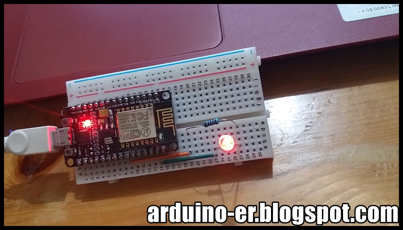
Tuesday, May 23, 2017

Control GPIOs of NodeMCU (ESP8266) with ESP8266 core for Arduino, to read Buttons and write LEDs

This example show how to read input (D5, D6 & D7) from buttons, and write output (D0, D1 & D2) to LEDs accordingly. For the input, all set INPUT_PULLUP to enable internal pull-up resistor, so no external resistors needed.


Connection:

/*
NodeMCU IO index vs ESP8266 pin
IO index  ESP8266 pin
    0     [*] GPIO16
    1     GPIO5 
    2     GPIO4 
    3     GPIO0
    4     GPIO2
    5     GPIO14  
    6     GPIO12
    7     GPIO13
    8     GPIO15
    9     GPIO3
    10    GPIO1
    11    GPIO9
    12    GPIO10
[*] D0(GPIO16) can only be used as gpio read/write. 
No support for open-drain/interrupt/pwm/i2c/ow.
https://nodemcu.readthedocs.io/en/master/en/modules/gpio/
 */
 
void setup() {
  pinMode(D0, OUTPUT);
  pinMode(D1, OUTPUT);
  pinMode(D2, OUTPUT);
  pinMode(D5, INPUT_PULLUP);
  pinMode(D6, INPUT_PULLUP);
  pinMode(D7, INPUT_PULLUP);
}

// the loop function runs over and over again forever
void loop() {
  if(digitalRead(D5)){
    digitalWrite(D0, LOW);
  }else{
    digitalWrite(D0, HIGH);
  }

  if(digitalRead(D6)){
    digitalWrite(D1, LOW);
  }else{
    digitalWrite(D1, HIGH);
  }

  if(digitalRead(D7)){
    digitalWrite(D2, LOW);
  }else{
    digitalWrite(D2, HIGH);
  }

}


Usage of GPIO:
At the beginning, I want to use D6, D7 and D8 as input. But D8 always return LOW. After googled and found schematic diagram of NodeMCU DevKit v1.0 here: https://github.com/nodemcu/nodemcu-devkit-v1.0/blob/master/NODEMCU_DEVKIT_V1.0.PDF. It's found that GPIO15 (D8) connect to GND via a resistor, so always return LOW.

And MATTERS NEEDING ATTENTION can be found in the schematic diagram:
On every boot/reset/wakeup, GPIO15 MUST keep LOW, GPIO2 MUST keep HIGH. 
GPIO0 HIGH -> RUN MODE, LOW -> FLASH MODE.
When you need to use the sleep mode, GPIO16 and RST should be connected, and GPIO16 will output LOW to reset the system at the time of wakeup.

So, I change using D5.


Monday, May 15, 2017

Nextion Project

This playlist created by ITEAD Studio, with DEMOs of Nextion Display and Nextion Editor.

Wednesday, May 10, 2017

Control GPIO (external IO pins) of NodeMCU (ESP8266) with ESP8266 core for Arduino


With ESP8266 core for Arduino, we can load and run the build-in basic example of "Blink" on NodeMCU to toggle the on board LED. We can also employ the same methods to control other io pin, or GPIO.


Connection:


There are many version of ESP8266, the printed mark on PCB may not the io number of ESP8266 MCU, you have to check it for your board. This example run on NodeMCU with marking and CPU pin assignment:
NodeMCU IO index vs ESP8266 pin
IO index  ESP8266 pin
    0     [*] GPIO16  
    1     GPIO5 
    2     GPIO4 
    3     GPIO0 
    4     GPIO2 
    5     GPIO14  
    6     GPIO12
    7     GPIO13
    8     GPIO15
    9     GPIO3
    10    GPIO1
    11    GPIO9
    12    GPIO10
[*] D0(GPIO16) can only be used as gpio read/write. 
No support for open-drain/interrupt/pwm/i2c/ow.
https://nodemcu.readthedocs.io/en/master/en/modules/gpio/

If you run on NodeMCU and select board of NodeMCU 1.0, you can use D1~D10 to access the pins. Refer to pins_arduino.h. Both D1 and 5 refer to the same pin.


If you run on other module, and select other board, may be the compile will report error of  'D1' was not declared in this scope. You have to specify the io# of the MCU, 5 in this case.


NodeMCU_Blink.ino
/*
NodeMCU IO index vs ESP8266 pin
IO index  ESP8266 pin
    0     [*] GPIO16  
    1     GPIO5 
    2     GPIO4 
    3     GPIO0 
    4     GPIO2 
    5     GPIO14  
    6     GPIO12
    7     GPIO13
    8     GPIO15
    9     GPIO3
    10    GPIO1
    11    GPIO9
    12    GPIO10
[*] D0(GPIO16) can only be used as gpio read/write. 
No support for open-drain/interrupt/pwm/i2c/ow.
https://nodemcu.readthedocs.io/en/master/en/modules/gpio/
 */

/*
 * For NodeMCU (8266) both D1 and 5 refer to the same pin
 * For others, such as "Generic ESP8266 Module", it will
 * report error of: 'D1' was not declared in this scope.
 */
const int io5 = 5;

// the setup function runs once when you press reset or power the board
void setup() {
  // initialize digital pins as an output.
  pinMode(LED_BUILTIN, OUTPUT);
  //pinMode(D1, OUTPUT);
  pinMode(io5, OUTPUT);
}

// the loop function runs over and over again forever
void loop() {
  digitalWrite(LED_BUILTIN, HIGH);
  //digitalWrite(D1, HIGH);
  digitalWrite(io5, HIGH);
  delay(500);
  //digitalWrite(D1, LOW);
  digitalWrite(io5, LOW);
  delay(500);
  digitalWrite(LED_BUILTIN, LOW);
  //digitalWrite(D1, HIGH);
  digitalWrite(io5, HIGH);
  delay(500);
  //digitalWrite(D1, LOW);
  digitalWrite(io5, LOW);
  delay(500);
}

Next:
Control GPIOs of NodeMCU (ESP8266) with ESP8266 core for Arduino, to read Buttons and write LEDs