Saturday, January 31, 2015

Use Arduino Uno as ISP to burn Bootloader on ATmega328

This post show how to use Arduino Uno as "Arduino as ISP", to burn bootloader on a empty ATmega328, marked ATMEGA328P-PU.

Extra components needed:
- a 16 MHz crystal,
- a 10k resistor, and
- two 22 picofarad capacitors.
Steps:


Program your Arduino Uno to be "Arduino as ISP":
- Connect Arduino Uno to PC with USB cable.
- Select Tools -> Port and your current connected Board (Arduino Uno).
- Select File -> Examples of ArduinoISP.
- Compile and upload to your Arduino Uno board.
- Once finished, your Arduino Uno is a "Arduino as ISP" now.

Burn bootloader to Atmega328, using your "Arduino as ISP":
- Select Tools -> Board, it is the board on which you want to burn the bootloader, not your current connect board. I will use Arduino Uno as target to verify my steps and setup later, so I keep using Arduino Uno.
- Select Tools -> Programmer of "Arduino as ISP".
- Select Tools -> Burn Bootloader
- Done.

Verify:
- Disconnect USB cable between Arduino Uno and yout PC.
- Replace the ATmega328 controller on your Arduino Uno with the new burnt ATmega328.
- Connect to PC again and try any example, it should be work as your original Arduino Uno.

Remark:

(I)
I have one chance failed with the error:

Arduino: 1.5.7 (Linux), Board: "Arduino Uno"

avrdude: Yikes!  Invalid device signature.
         Double check connections and try again, or use -F to override
         this check.

  This report would have more information with
  "Show verbose output during compilation"
  enabled in File > Preferences.

It is caused by bad contact, solved by slightly fixing the wires.

(II)
Mention in the tutorial "Using an Arduino as an AVR ISP (In-System Programmer)": Note for the Arduino Uno: you'll need to add a 10 uF capacitor between reset and ground.

In my trial experience, I have no this capacitor added.


Reference:
http://arduino.cc/en/Tutorial/ArduinoToBreadboard
- http://arduino.cc/en/Tutorial/ArduinoISP

Saturday, January 24, 2015

123D Circuits - Blink LED with an Arduino

This video shows how to use an Arduino UNO to blink a LED in 123D Circuits. Anyone can do this, the "blinky" code is already pre-loaded into every Arduino in the 123D Circuits, just open a new Breadboard simulation file and you're off and blinking!

Link to the actual circuit in the video:
http://123d.circuits.io/circuits/546245


Visit: http://123d.circuits.io/

Thursday, January 22, 2015

Arduino Uno + SPI 8x8 LED Matrix, with MAX7219 LED driver

MAX7219 is a LED Driver from Maxim to drive either 64 individual Led's, or up to 8 digits of 7-segment displays. The drivers implement a SPI compatible slave interface that can be controlled from the Arduino using only 3 of the digital output pins. Know more about MAX7219, and MAX7221, refer to http://playground.arduino.cc/Main/MAX72XXHardware.


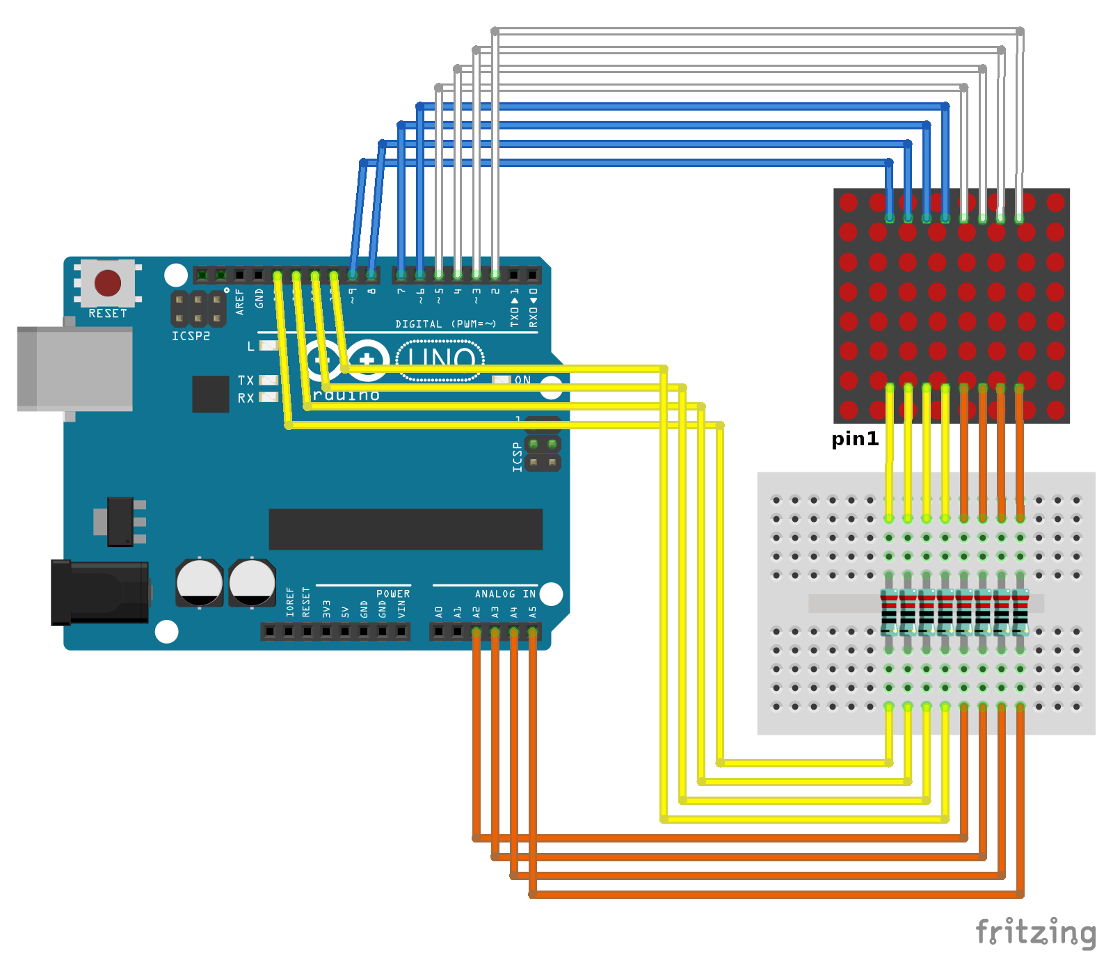
This example show how Arduino Uno work with DIY boeard of SPI 8x8 LED Matrix, with MAX7219 LED driver and 1088AS row cathode column anode 8x8 LED Matrix.


Visit http://playground.arduino.cc/LEDMatrix/Max7219, copy the sample sketch and un-comment your expected pattern to display.

//reference: http://playground.arduino.cc/LEDMatrix/Max7219

/* code for max 7219 from maxim, 
reduced and optimised for useing more then one 7219 in a row,
______________________________________

 Code History:
 --------------

The orginal code was written for the Wiring board by:
 * Nicholas Zambetti and Dave Mellis /Interaction Design Institute Ivrea /Dec 2004
 * http://www.potemkin.org/uploads/Wiring/MAX7219.txt

First modification by:
 * Marcus Hannerstig/  K3, malm� h�gskola /2006
 * http://www.xlab.se | http://arduino.berlios.de

This version is by:
 * tomek ness /FH-Potsdam / Feb 2007
 * http://design.fh-potsdam.de/ 

 * @acknowledgements: eric f. 

-----------------------------------

General notes: 


-if you are only using one max7219, then use the function maxSingle to control
 the little guy ---maxSingle(register (1-8), collum (0-255))

-if you are using more then one max7219, and they all should work the same, 
then use the function maxAll ---maxAll(register (1-8), collum (0-255))

-if you are using more than one max7219 and just want to change something
at one little guy, then use the function maxOne
---maxOne(Max you wane controll (1== the first one), register (1-8), 
collum (0-255))

/* During initiation, be sure to send every part to every max7219 and then
 upload it.
For example, if you have five max7219's, you have to send the scanLimit 5 times
before you load it-- other wise not every max7219 will get the data. the
function maxInUse  keeps track of this, just tell it how many max7219 you are
using.
*/

int dataIn = 2;
int load = 3;
int clock = 4;

int maxInUse = 4;    //change this variable to set how many MAX7219's you'll use

int e = 0;           // just a varialble

                     // define max7219 registers
byte max7219_reg_noop        = 0x00;
byte max7219_reg_digit0      = 0x01;
byte max7219_reg_digit1      = 0x02;
byte max7219_reg_digit2      = 0x03;
byte max7219_reg_digit3      = 0x04;
byte max7219_reg_digit4      = 0x05;
byte max7219_reg_digit5      = 0x06;
byte max7219_reg_digit6      = 0x07;
byte max7219_reg_digit7      = 0x08;
byte max7219_reg_decodeMode  = 0x09;
byte max7219_reg_intensity   = 0x0a;
byte max7219_reg_scanLimit   = 0x0b;
byte max7219_reg_shutdown    = 0x0c;
byte max7219_reg_displayTest = 0x0f;

void putByte(byte data) {
  byte i = 8;
  byte mask;
  while(i > 0) {
    mask = 0x01 << (i - 1);      // get bitmask
    digitalWrite( clock, LOW);   // tick
    if (data & mask){            // choose bit
      digitalWrite(dataIn, HIGH);// send 1
    }else{
      digitalWrite(dataIn, LOW); // send 0
    }
    digitalWrite(clock, HIGH);   // tock
    --i;                         // move to lesser bit
  }
}

void maxSingle( byte reg, byte col) {    
//maxSingle is the "easy"  function to use for a     //single max7219

  digitalWrite(load, LOW);       // begin     
  putByte(reg);                  // specify register
  putByte(col);//((data & 0x01) * 256) + data >> 1); // put data   
  digitalWrite(load, LOW);       // and load da shit
  digitalWrite(load,HIGH); 
}

void maxAll (byte reg, byte col) {    // initialize  all  MAX7219's in the system
  int c = 0;
  digitalWrite(load, LOW);  // begin     
  for ( c =1; c<= maxInUse; c++) {
  putByte(reg);  // specify register
  putByte(col);//((data & 0x01) * 256) + data >> 1); // put data
    }
  digitalWrite(load, LOW);
  digitalWrite(load,HIGH);
}

void maxOne(byte maxNr, byte reg, byte col) {    
//maxOne is for adressing different MAX7219's, 
//whilele having a couple of them cascaded

  int c = 0;
  digitalWrite(load, LOW);  // begin     

  for ( c = maxInUse; c > maxNr; c--) {
    putByte(0);    // means no operation
    putByte(0);    // means no operation
  }

  putByte(reg);  // specify register
  putByte(col);//((data & 0x01) * 256) + data >> 1); // put data 

  for ( c =maxNr-1; c >= 1; c--) {
    putByte(0);    // means no operation
    putByte(0);    // means no operation
  }

  digitalWrite(load, LOW); // and load da shit
  digitalWrite(load,HIGH); 
}


void setup () {


  pinMode(dataIn, OUTPUT);
  pinMode(clock,  OUTPUT);
  pinMode(load,   OUTPUT);

  //beginSerial(9600);
  digitalWrite(13, HIGH);  

//initiation of the max 7219
  maxAll(max7219_reg_scanLimit, 0x07);      
  maxAll(max7219_reg_decodeMode, 0x00);  // using an led matrix (not digits)
  maxAll(max7219_reg_shutdown, 0x01);    // not in shutdown mode
  maxAll(max7219_reg_displayTest, 0x00); // no display test
   for (e=1; e<=8; e++) {    // empty registers, turn all LEDs off 
    maxAll(e,0);
  }
  maxAll(max7219_reg_intensity, 0x0f & 0x0f);    // the first 0x0f is the value you can set
                                                  // range: 0x00 to 0x0f
}  

void loop () {


  //if you use just one MAX7219 it should look like this
  /*
   maxSingle(1,1);                       //  + - - - - - - -
   maxSingle(2,2);                       //  - + - - - - - -
   maxSingle(3,4);                       //  - - + - - - - -
   maxSingle(4,8);                       //  - - - + - - - -
   maxSingle(5,16);                      //  - - - - + - - -
   maxSingle(6,32);                      //  - - - - - + - -
   maxSingle(7,64);                      //  - - - - - - + -
   maxSingle(8,128);                     //  - - - - - - - +
  */

  //if you use more than one MAX7219, it should look like this
  
  maxAll(1,1);                       //  + - - - - - - -
  maxAll(2,3);                       //  + + - - - - - -
  maxAll(3,7);                       //  + + + - - - - -
  maxAll(4,15);                      //  + + + + - - - -
  maxAll(5,31);                      //  + + + + + - - -
  maxAll(6,63);                      //  + + + + + + - -
  maxAll(7,127);                     //  + + + + + + + -
  maxAll(8,255);                     //  + + + + + + + +
  
  //

  //if you use more then one max7219 the second one should look like this


  maxOne(2,1,1);                       //  + - - - - - - -
  maxOne(2,2,2);                       //  - + - - - - - -
  maxOne(2,3,4);                       //  - - + - - - - -
  maxOne(2,4,8);                       //  - - - + - - - -
  maxOne(2,5,16);                      //  - - - - + - - -
  maxOne(2,6,32);                      //  - - - - - + - -
  maxOne(2,7,64);                      //  - - - - - - + -
  maxOne(2,8,128);                     //  - - - - - - - +


  // 
  delay(2000);

}

For this example, connect the pins between the DIY board and Uno board.
  • VCC - Uno 5V
  • GND - Uno GND
  • DIN - Uno 2
  • CS - Uno 3
  • CLK - Uno 4
Below video show soldering and assembling the DIY kit of SPI 8x8 LED Matrix board.


If you need to identify the pin 1 of the 1088AS 8x8 LED Matrix, refer to last post "How to identify pin 1 of 8x8 LED Matrix", part II.

More about Controlling a Led matrix or 7-segment displays with the MAX7219 or the MAX7221, in Arduino Playground.

Related:
Arduino Uno + MAX7219 8x8 LED Matrix via SPI, using LedControl Library

Thursday, January 15, 2015

How to identify pin 1 of 8x8 LED Matrix

This post show how to identify pin 1, and pin 16, of 8x8 LED Matrix.


Part I: Row Anode Column Cathode 8x8 LED Matrix, 1588BS as example. Current flow from pin 1 to pin 16 to make LED on row 5 col 8 ON.

Use the example of Row-Column Scanning an 8x8 LED matrix to show it work.

The connection between Arduino Uno and 8x8 LED Matrix is show here:

(It's recommended to add 220 ohm resisters to limit the current)

We need a test program to verify our connection, visit http://goo.gl/tXySxV, copy the example sketch of Walking bit on 8*8 LED Matrix, and download to Arduino Uno.


If your 8x8 LED Matrix have no marking for pin 1, we can use a multimeter to identify pin 1, and also pin 16.

This scheme diagram show when we apply +ve on pin 1 and -ve on pin 16, the LED on row 5 col 8 will be turn on.

Switch multimeter to diode test, the red lead will be +ve and black lead will be -ve.

Refer to the below video:
There are 4 possibility of pin 1 and 16, only one case will turn on a LED. When the LED (row 5 col 8) on, the pin connected to the RED lead of multimeter is pin 1.


Part II: Row Cathode Column Anode 8x8 LED Matrix, 1088AS as example. Current flow from pin 16 to pin 1 to make LED on row 5 col 8 ON.


Same procedure as in part I, with pin 1 on BLACK lead of multimeter.


Working example, refer to next post "Arduino Uno + SPI 8x8 LED Matrix, with MAX7219 LED driver".


Friday, January 9, 2015

Web Server example run on Arduino Uno with Ethernet Shield

Web Server example run on Arduino Uno with Ethernet Shield.


WebServer.ino
/*
 *  Reference: http://arduino.cc/en/Tutorial/WebServer
 */
#include <SPI.h>
#include <Ethernet.h>

// Enter a MAC address and IP address for your controller below.
// The IP address will be dependent on your local network:
byte mac[] = {
  0xDE, 0xAD, 0xBE, 0xEF, 0xFE, 0xED
};
IPAddress ip(192, 168, 1, 177);

// Initialize the Ethernet server library
// with the IP address and port you want to use
// (port 80 is default for HTTP):
EthernetServer server(80);

void setup() {
  // Open serial communications and wait for port to open:
  Serial.begin(9600);
  while (!Serial) {
    ; // wait for serial port to connect. Needed for Leonardo only
  }

  // start the Ethernet connection and the server:
  Ethernet.begin(mac, ip);
  server.begin();
  Serial.print("server is at ");
  Serial.println(Ethernet.localIP());
}


void loop() {
  // listen for incoming clients
  EthernetClient client = server.available();
  if (client) {
    Serial.println("new client");
    // an http request ends with a blank line
    boolean currentLineIsBlank = true;
    while (client.connected()) {
      if (client.available()) {
        char c = client.read();
        Serial.write(c);
        // if you've gotten to the end of the line (received a newline
        // character) and the line is blank, the http request has ended,
        // so you can send a reply
        if (c == '\n' && currentLineIsBlank) {
        
          client.println("<!DOCTYPE html>");
          client.println("<html>");
          client.print("<h1>hello Arduino Ethernet Shield</h1>");
          client.println("</html>");
          break;
        }
        if (c == '\n') {
          // you're starting a new line
          currentLineIsBlank = true;
        }
        else if (c != '\r') {
          // you've gotten a character on the current line
          currentLineIsBlank = false;
        }
      }
    }
    // give the web browser time to receive the data
    delay(1);
    // close the connection:
    client.stop();
    Serial.println("client disconnected");
  }
}

Reference:


Friday, January 2, 2015

Using a RFID Card Reader with the Arduino


This tutorial was developed for the MAKE course at the University of South Florida (www.makecourse.com). This tutorial discusses the use of a MF522-AN RFID reader and MIFARE Classic 1k tags/cards with the Arduino. The basics of RFID communication are reviewed as well as the MIFARE card hardware. A library for the MF522 that can be found at github (https://github.com/miguelbalboa/rfid) is being used for a simple Arduino sketch that allows the writing and reading of blocks on a MIFARE card.


Related:
- Mifare MFRC522 RFID Reader/Writer

Thursday, January 1, 2015

Happy New Year 2015 - LCD Scrolling example


#include <LiquidCrystal.h>

// initialize the library with the numbers of the interface pins
LiquidCrystal lcd(12, 11, 5, 4, 3, 2);

void setup() {
  // set up the LCD's number of columns and rows: 
  lcd.begin(16, 2);
  // Print a message to the LCD.
  lcd.setCursor(0, 0);
  lcd.print(" Happy New Year ");
  lcd.setCursor(0, 1);
  lcd.print("      2015      ");
  delay(3000);
}

void loop() {
  // scroll 13 positions (string length) to the left 
  // to move it offscreen left:
  for (int positionCounter = 0; positionCounter < 15; positionCounter++) {
    // scroll one position left:
    lcd.scrollDisplayLeft(); 
    // wait a bit:
    delay(1000);
  }

  // scroll 29 positions (string length + display length) to the right
  // to move it offscreen right:
  for (int positionCounter = 0; positionCounter < 30; positionCounter++) {
    // scroll one position right:
    lcd.scrollDisplayRight(); 
    // wait a bit:
    delay(1000);
  }
  
  for (int positionCounter = 0; positionCounter < 15; positionCounter++) {
    // scroll one position left:
    lcd.scrollDisplayLeft(); 
    // wait a bit:
    delay(1000);
  }
  
  // delay at the end of the full loop:
  delay(3000);

}


Example: LiquidCrystal - scrollDisplayLeft() and scrollDisplayRight()